Fire & Heat Event Detection
Fire and heat monitoring can involve several different technologies: visual analytics, thermal imaging, temperature measurement and dedicated fire detection systems. The right starting point is the condition a customer needs to understand. A supported camera or sensor may help identify a configured heat-related event and provide information for review, but operational analytics must remain distinct from required certified fire and life-safety protection.
Video unavailable. Follow the illustrated workflow below.
THE EVENT JOURNEY
Equipment surface → thermal rule → escalation
Monitor equipment
A thermal or supported video source observes a defined equipment area.
Evaluate a change
A configured thermal threshold or visual event can raise a candidate where the selected platform supports it.
Deliver context
Facilities or monitoring staff receive the location and available event information through approved interfaces.
Review and escalate
Qualified staff follow the site procedure. Supplementary analytics does not replace required fire or life-safety systems.
Illustrative sequence, not a detection-speed demonstration. Capabilities and notification channels depend on the selected equipment, platform and agreed response workflow.
Define the condition before selecting equipment
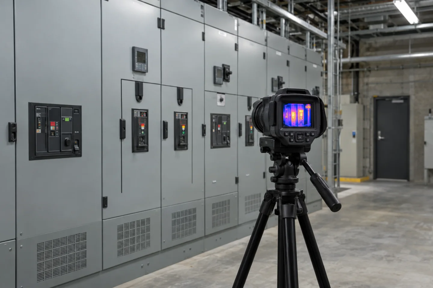
A visual flame indication, a surface temperature threshold and an abnormal temperature trend are not interchangeable measurements. A conventional camera does not measure temperature simply because it shows an image. A thermal camera may provide a thermal view, while a temperature-monitoring model may support specific measurement functions.
The chosen equipment, application and calibration arrangements determine which features are available.
For an equipment-monitoring project, the scope might be a visible motor housing, a defined process area or an accessible surface on installed plant. Agree what is being observed, the relevant operating states and the threshold or rule to be reviewed.
Avoid presenting a single camera view as a complete assessment of the equipment or of fire risk throughout a building.
Understand the measurement boundaries
Thermal readings depend on the selected device and the conditions in the scene. Viewing geometry, distance, surface characteristics, reflections, obstructions and environmental changes can influence interpretation. Enclosures and barriers may prevent the camera from observing the condition of interest. A useful design records these limitations and checks whether a dedicated contact sensor or another specialist method is more appropriate.
Visible fire analytics introduces a different set of scene and feature dependencies. It should be described as a supported application for a configured view, not a universal ability of every CCTV system. Where the site requires certified detection, alarm or suppression arrangements, those systems retain their own design, testing and response requirements.
Supplementary camera information must not be used to bypass them.
Apply the information to operational decisions
Industrial sites may use suitable thermal monitoring to bring an equipment condition to a maintenance team's attention. Warehouses and commercial facilities may need an additional visual review route for specific plant or technical spaces. Remote installations may benefit from a supported sensor or camera event that gives an off-site operator context before arranging attendance.
A trend or threshold notification can support a maintenance investigation, while a suspected fire-related event may require the site's established emergency escalation. These outcomes should not share an ambiguous generic message. Agree the event classes, recipients and expected action with the responsible technical and safety teams.
The interface should help people distinguish a maintenance condition from an alarm originating in a dedicated safety system.
Deliver the event through a secure workflow
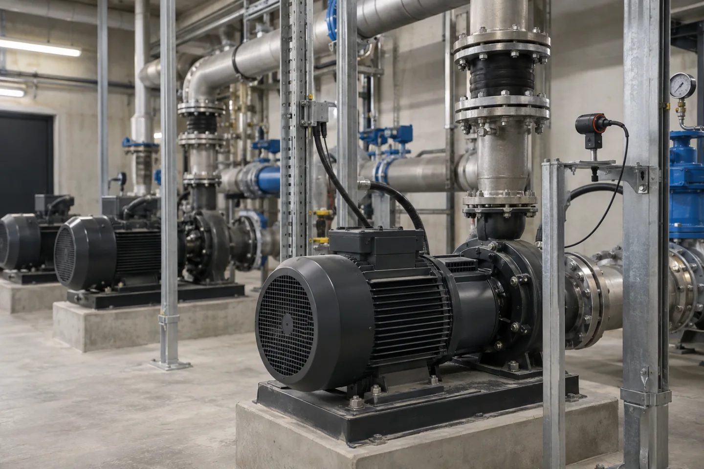
A compatible camera, sensor gateway or analytics platform can generate an event containing the configured zone, time, condition and available supporting information. That event may be routed through the local network to a VMS, monitoring dashboard or secure remote platform.
Email, text/SMS, app notifications and control room alerts depend on the supported integration and the chosen receiving service.
If an alarm output or connection to another control system is proposed, define exactly what it is permitted to do. An operational output is not automatically a certified safety interface. Human review, acknowledgement and escalation should be documented, including what happens when a recipient is unavailable.
The network design should make a lost link or failed device distinguishable from normal operation with no events.
Commission and maintain the agreed capability
Testing should use safe, approved procedures appropriate to the selected equipment and site. Do not create a fire or expose equipment to unsafe temperatures to prove an analytics feature. Validate the rule settings, available event evidence, destination routing and fault reporting.
Record the conditions under which the demonstration was accepted and any circumstances that require another monitoring method.
Review the system when equipment is replaced, camera positions change or operating conditions differ from the original scope. Administration access, firmware maintenance, retained images and event records need agreed ownership. IS Security can coordinate the installation, network and integration work around a supported monitoring platform, while the appropriate specialists remain responsible for any required certified fire or life-safety system design and approval.
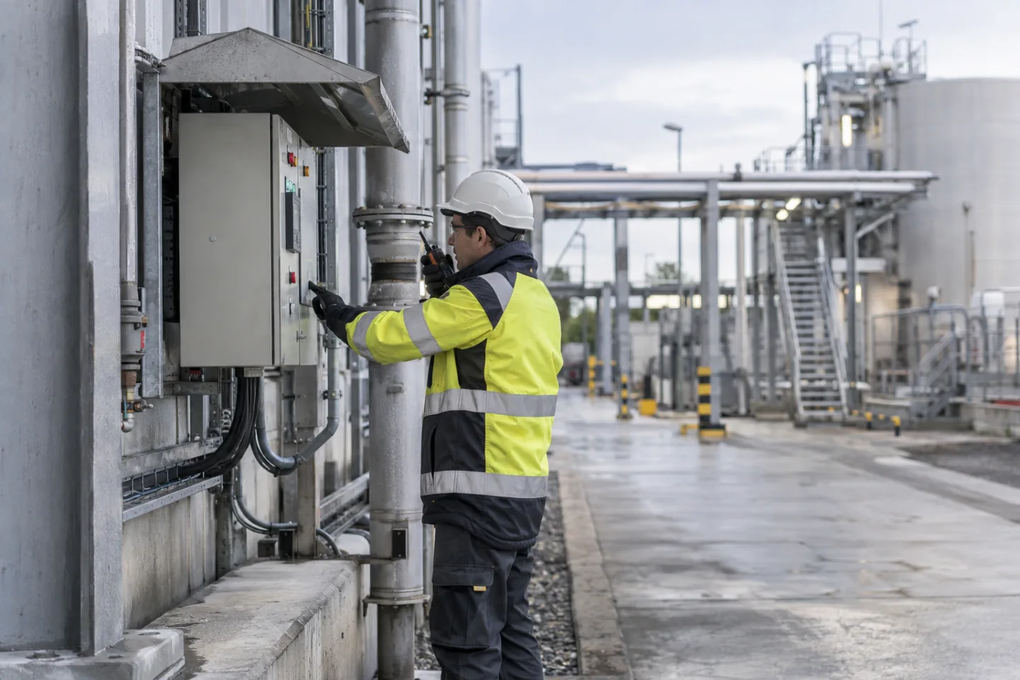
From a possible event to a useful response.
Equipment surface → thermal rule → escalation. Open each stage to explore its role. This is an illustrative workflow; it does not analyse live footage or send notifications.
01 / OBSERVEThermal camera / supported sensor
The monitored condition is: temperature trend or visual event. Select the device, field of view and installation position for this specific task. Record obstructions, lighting, power and maintenance requirements before relying on the event stream.
02 / INTERPRETThermal / video analysis platform
Apply configured threshold and persistence. The selected platform must support the intended event and expose a usable interface. Test representative events and unwanted triggers; an analytics output is a candidate for review, not proof of what happened.
03 / CONNECTLAN → firewall → secure platform
Carry authorised event data through the local switch or sensor gateway and an approved network path. Size bandwidth for any accompanying clip. Protect accounts and interfaces, supervise connection loss and agree retry behaviour where the platform supports it.
04 / RESPONDFacilities / monitoring operator
Deliver the location, event type and time to the agreed recipient. A person verifies the available context, follows the site response procedure and records the outcome. Delivery, acknowledgement and resolution are different states and should be reviewed separately.
Where supported by the selected camera, sensor, VMS or analytics platform. Safety-related analytics provide supplementary operational awareness and do not replace dedicated certified fire or life-safety systems where required. The final design must define the equipment, event interfaces and responsible response team.
Reach the people who can act.
Available outputs depend on the selected platform, licences and agreed integrations. Open a channel for practical delivery considerations.
Send event context and a secure review link to an authorised mailbox where supported. Agree recipients and inbox monitoring; acceptance by a mail server does not confirm that a person has read or acted on the message.
Text / SMS
Use a supported gateway or monitoring integration for concise location and priority messages. Confirm service availability, costs and delivery reporting. Sensitive footage should stay within the authorised platform rather than an unrestricted text message.
Mobile apps
A supported application can present event details and acknowledgement controls to authorised users. Test notification permissions, connectivity and out-of-hours coverage. A silenced or offline handset needs a planned alternative recipient or escalation route.
Alarm outputs
A compatible interface may trigger an approved operational sounder, relay or indicator. Define supervision, reset behaviour and responsibility. Do not connect analytics directly to hazardous equipment or alter certified safety functions without the appropriate engineered design.
Control room / monitoring platform
Route supported events into the operator workflow with a consistent site identifier and priority. Give reviewers enough context to distinguish an actionable event from an unwanted trigger, with access restricted to their responsibilities.
Escalation & event review
Define who receives an unacknowledged event, how long the initial team has to respond and how closure is recorded. Review failed deliveries, recurring unwanted alerts and staffing gaps alongside the detection rules.
Plan the complete monitoring chain.
Start with the event, the operating environment and the person responsible for responding. Share existing equipment details, site plans and integration requirements with the technical team.