01
Backbone routes
Fibre runs between network cabinets and equipment locations across the vessel, based on an agreed route and specification.


Fibre backbone installation, replacement and connection work for commercial vessel networks.
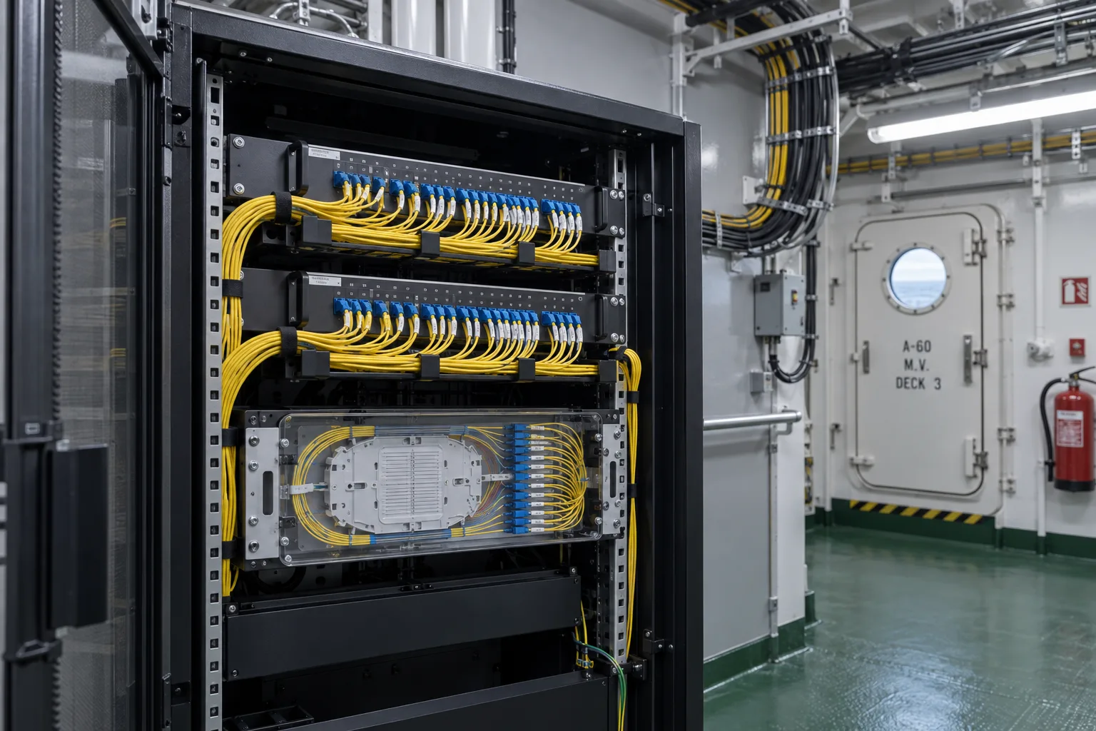
Distributed equipment spaces require a clear plan for fibre routing, terminations and connections. IS Security installs onboard fibre infrastructure and coordinates it with the active network equipment. We scope each run around the vessel layout, existing routes and the intended system.
Physical infrastructure, connected equipment and a clearly agreed installation scope.
Fibre runs between network cabinets and equipment locations across the vessel, based on an agreed route and specification.
Review onboard access, containment and coordination needs before cable installation begins.
Provide organised termination and patching at the network locations served by the backbone.
Coordinate the fibre connections with compatible switch interfaces and existing onboard equipment.
Check installed connections and provide the agreed identification and test information at handover.
Investigate fibre connection problems, replace affected cabling and support planned backbone upgrades.
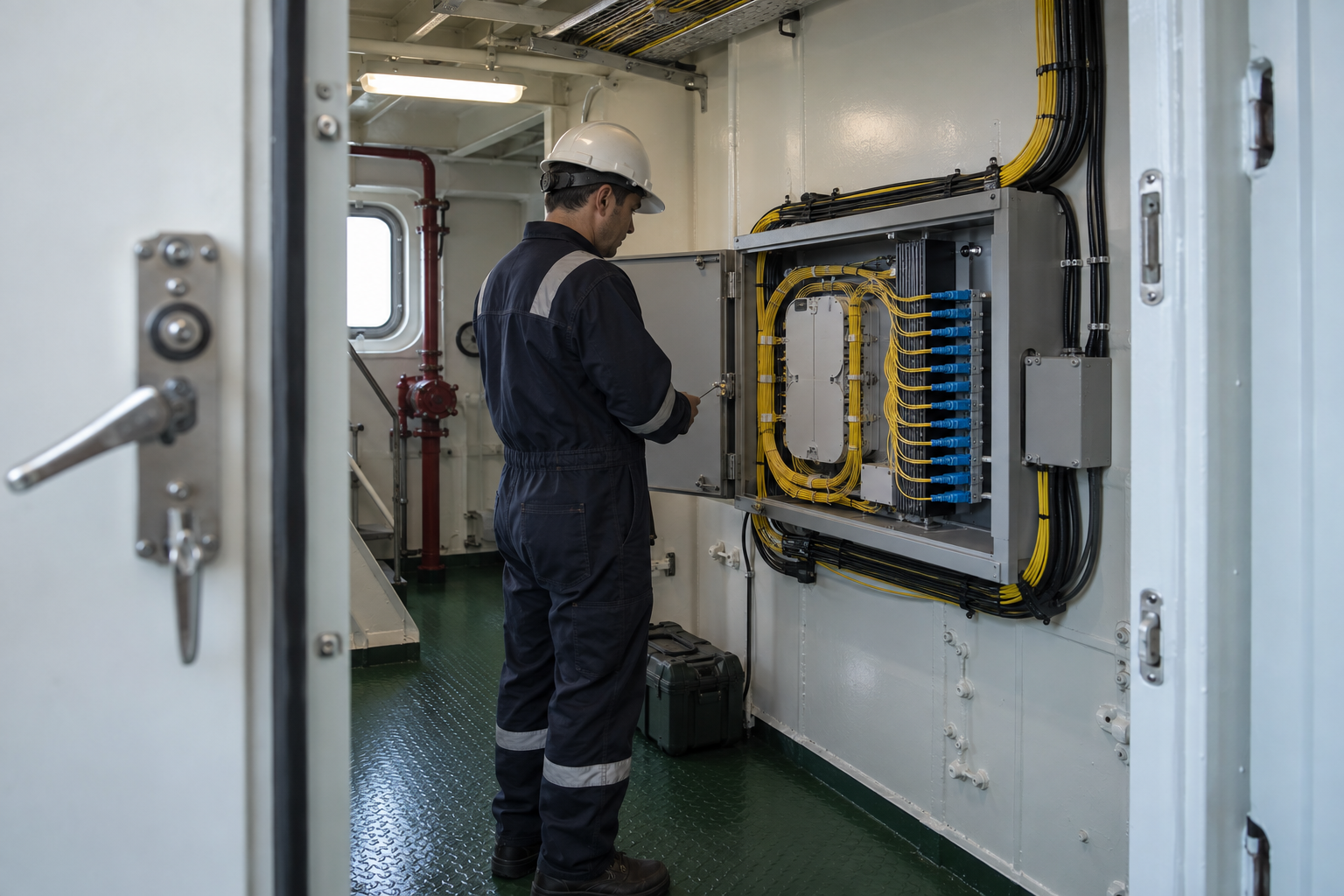
Vessel location, cable access, interfaces and attendance windows shape the agreed installation. The diagram illustrates system relationships, not a completed vessel project.
Scope an onboard optical backbone, repair or fibre extension. Explore the decisions that shape the installation, interfaces and handover.
Shipboard fibre planning needs the equipment information at both ends, not only a route drawing. Confirm the existing fibre type, core availability, termination arrangement and compatible optical modules. If records are uncertain, identify what must be inspected before materials are finalised. A mismatch discovered after boarding may be difficult to resolve within the port window. Record which parts of the link are new, retained or supplied by another contractor, and make responsibility for active-equipment configuration explicit in the agreed scope.
Fibre management must remain serviceable in the vessel’s available technical spaces. Review where trays, patching and spare fibre will sit, how access is obtained and how the route is protected. Material selection and any compartment interfaces should follow the vessel’s approved requirements. Avoid assuming that an existing pathway has spare usable capacity simply because it appears on an old drawing. Where a live backbone is being replaced, identify the systems using it and agree a changeover sequence with the team responsible for those services.
Agree the optical acceptance method, link identifiers and required records before attendance. Loss measurement, route investigation and active service verification should be distinguished so the client understands what each result establishes. Record the fibre pairs or cores used, endpoint locations and any unresolved limitation. Where the fleet team manages future support from shore, deliver the agreed record in a consistent format that can be matched to onboard labels. That evidence is more useful for later maintenance than an unlabelled image of an open tray.
Match fibre, connectors and supported optical interfaces at both ends.
Identify live dependencies and vessel-approved routing conditions.
Tie optical results and service checks to named onboard endpoints.
Use these checkpoints to discuss the scope. The final test method, responsibilities and acceptance evidence depend on the selected system and agreed work.
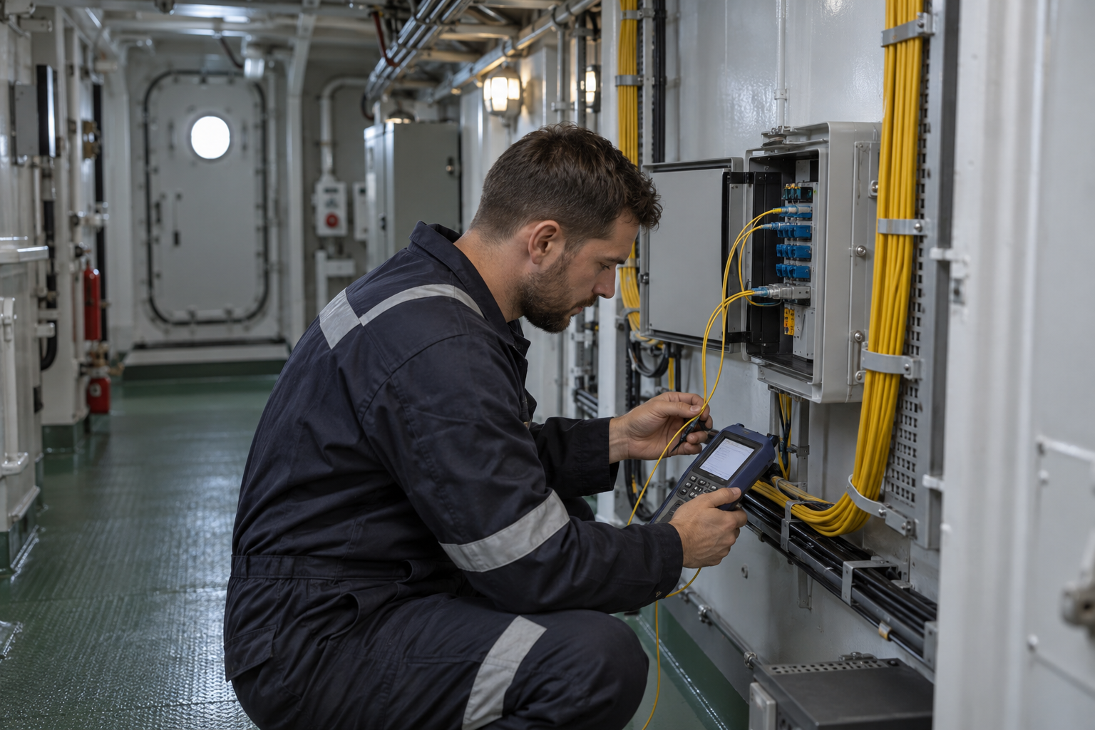
Vessel fibre installation needs a schedule of the equipment spaces being connected and the interfaces at both ends. Confirm existing fibre type, termination arrangements and spare cores proposed for use. Include distribution shelves, patch leads and fibre storage in the brief. The operator must confirm applicable material and route requirements; these cannot be inferred from an office specification. Establish which existing services use the backbone before arranging any interruption.
Onboard fibre routing may involve constrained spaces and routes shared with existing services. Review access to the intended trays and working space at each distribution point. Preserve manageable bends and protected storage at termination shelves, following the selected cable and equipment requirements. Agree responsibilities for specialist penetrations and reinstatement before attendance. A route that cannot be completed within the window needs a documented stopping point and a clearly recorded status.
Agree the required fibre tests and link the results to named endpoints and cores. Record retained links separately from new or repaired sections. Identify which compatible network interfaces were available for service checks. For an intermittent fault, document the circumstances and affected equipment before proposing replacement. Shore support should receive the same final route and termination information retained aboard, including untested portions or locations that could not be accessed.
Explore installation requirements, interfaces and the information needed before work begins.
Maritime fibre installation connects backbone locations that may be separated by several decks and working areas. Establish the existing fibre type, termination arrangements, available cores and network interfaces before choosing replacement or additional cable. Confirm access to each endpoint and the complete route with the vessel team.
Cable routing, handling and entry into cabinets need to suit the agreed vessel specification. Copper links can remain the local connection to devices while fibre connects network locations. Machinery-space access and other restricted areas are coordinated as part of attendance rather than treated as ordinary office access.
For a failed link, provide the affected endpoints, switch details, any recent changes and existing records. Testing and inspection should distinguish a cable or termination issue from an equipment-interface problem. Agree the required measurements and reports before committing to a repair scope.
A new installation enquiry should include deck plans, proposed cabinet positions and the port window. Handover identifies routes, terminations, core allocation and agreed test results. International attendance and multi-vessel programmes require a review of access and equipment logistics; no vessel-class or offshore approval is implied.
Fibre can form part of the network linking CCTV equipment locations. The network layout, switches, cameras and recording equipment need to be considered together.
Existing route information, connection details, equipment types and known fault symptoms are helpful. We also need the vessel location and available access window.
Yes. Cable selection and installation requirements must be agreed against the vessel’s specification and responsible team’s requirements. We do not assume one cable type suits every onboard route.
Commercial sites. International programmes. Onboard systems.
Installations across all of the US, Europe, the Caribbean, the UK and South Africa, with deployment support in Canada and Panama.
Regional resources · Fly teams · International project support
Explore regions & deployment hubs → DEPLOYMENT NETWORK / ILLUSTRATIVE CONNECTIONS