01
Backbone installation
Fibre cabling between cabinets, floors and equipment spaces, coordinated with the surrounding copper and network infrastructure.


Fibre infrastructure for commercial backbones, distributed network cabinets and onboard vessel networks.
Fibre connects network locations across larger premises and vessel infrastructure. We plan installation around the required route, available access and the equipment at each end, so the backbone works as part of the wider network.
Physical infrastructure, connected equipment and a clearly agreed installation scope.
Fibre cabling between cabinets, floors and equipment spaces, coordinated with the surrounding copper and network infrastructure.
Review existing containment and access points before agreeing the route, cable specification and installation sequence.
Organised fibre termination and patching within cabinets, with suitable access and identification for future maintenance.
Match the physical fibre installation to the planned network connections and compatible equipment interfaces.
Test installed connections against the agreed scope and identify routes and terminations for handover.
Investigate link faults, replace damaged runs and extend fibre infrastructure when equipment or operational requirements change.
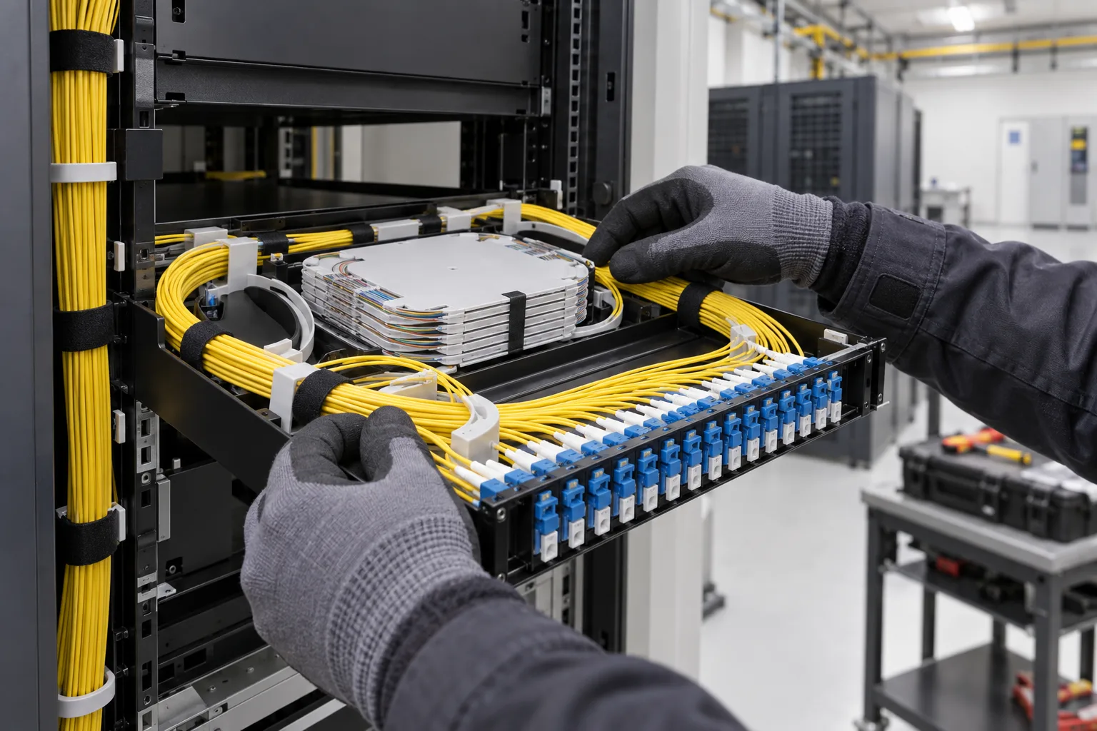
Routing, termination, patching and compatible interfaces are considered together.
Scope a commercial optical backbone or fibre replacement. Explore the decisions that shape the installation, interfaces and handover.
A fibre route needs a compatible connection at each end. Confirm the existing fibre type, available cores, connector arrangement and the network interfaces that will use it. The switch or media interface, optical module and installed fibre must be considered together; changing only the cable may not resolve an incompatible link. If records are incomplete, include investigation in the scope instead of assuming colour or connector appearance identifies the whole installation. Reserve a clear place for the termination tray and future maintenance access.
A building backbone may cross risers, service corridors or separate structures with very different access conditions. Review containment, environmental exposure, pulling access and how work will be coordinated with the building team. Fibre management inside the cabinet is part of this route, not an afterthought. Allow suitable storage and bend management for spare fibre and patch leads. Agree responsibilities for any building penetrations and reinstatement before attendance. For occupied sites, identify which services depend on existing optical links and how replacement will be sequenced.
Define the acceptance tests and the identification of both endpoints before commissioning. Optical loss testing and fault-location investigations answer different questions; specify the required evidence rather than asking for an unspecified fibre test. Results should reference the actual installed links, test configuration and agreed acceptance criteria. Where active equipment is included, verify the intended network service after physical testing. Keep unused cores, repaired sections and any limitations visible in the handover. This makes later fault investigation more focused and helps the site plan capacity without reopening every tray.
Confirm fibre, connectors and optical modules at both endpoints.
Review containment, environmental conditions and managed fibre storage.
Associate optical test records and service checks with the identified link.
Use these checkpoints to discuss the scope. The final test method, responsibilities and acceptance evidence depend on the selected system and agreed work.
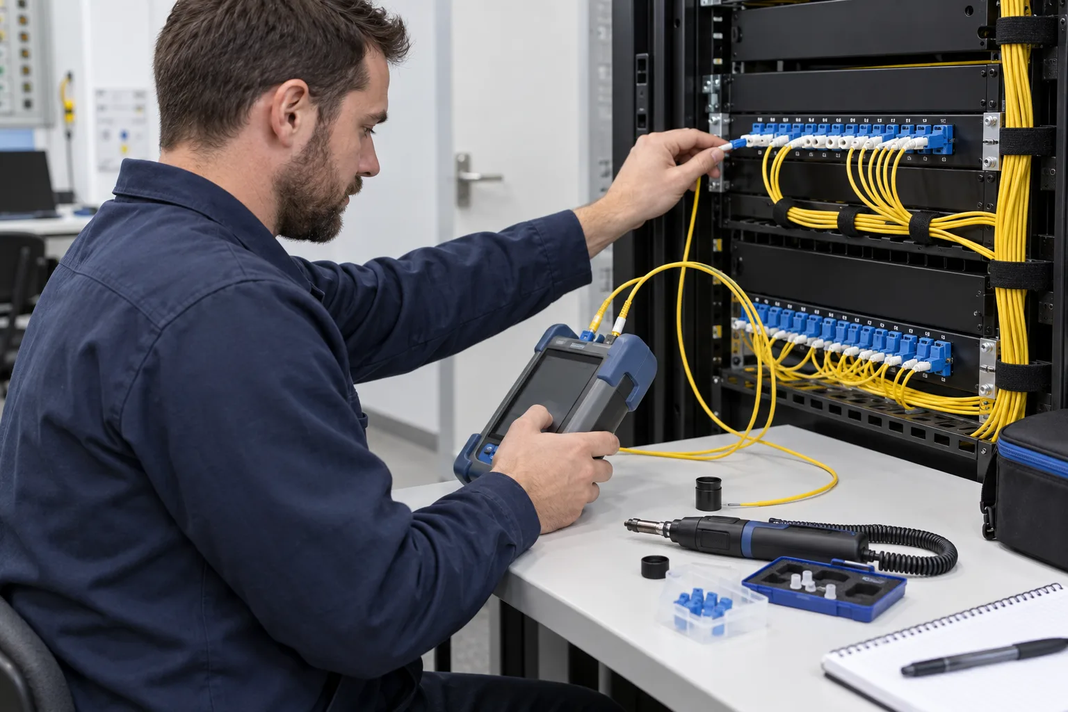
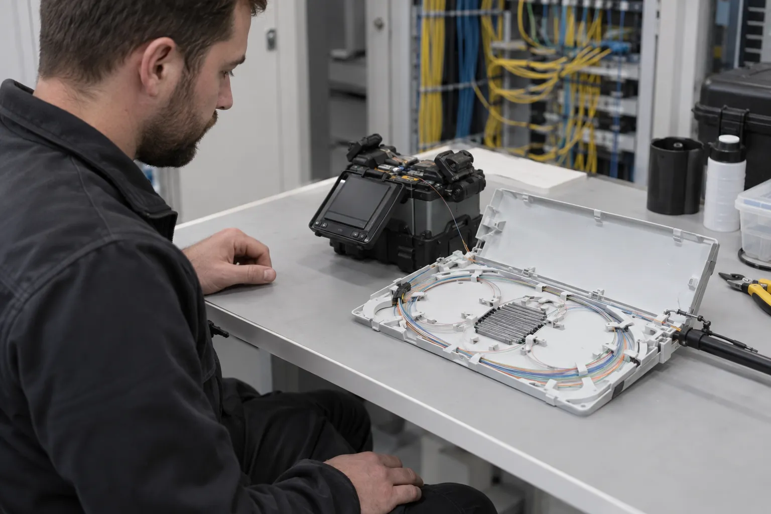
A fibre optic installation contractor needs to understand how each cabinet will be used. An office riser may connect several floor distributors, while a warehouse backbone may feed cabinets at opposite ends of the building. Record the origin, destination and intended use of each fibre before ordering cable. Include the distribution shelf, splice storage, adapters and patch leads in the equipment schedule. The resulting installation should leave individual connections accessible without disturbing adjacent live services. Spare cores are useful only when their destinations and termination status are documented.
Office fibre installation often involves shared risers and work outside occupied hours. Retail fibre routes may cross landlord areas before reaching a tenant communications cabinet. In warehouses, routes above racking need coordination with storage operations and access equipment. External runs require a separate assessment of the route, cable construction, entries and protection; an internal cable specification should not simply be extended outdoors. For vessel work, start with the dedicated maritime fibre scope, where onboard routes, protected penetrations and attendance windows shape the installation.
Agree the optical acceptance tests and required records before work begins. Inspection and cleaning of connector end faces precede meaningful measurements. Optical loss testing and OTDR investigation answer different questions; specify which records are required for the project rather than describing every test as certification. Keep results associated with the actual fibre identifiers and endpoints. When extending an existing backbone, identify available cores and interfaces first, then agree the interruption window and restoration plan. A completed handover should distinguish new links, retained infrastructure, repaired faults and any conditions that still limit service.
Equipment-specific reference: Fluke Networks: connector inspection and OTDR fault investigation.
Explore installation requirements, interfaces and the information needed before work begins.
Commercial fibre installation starts with the endpoints and the application. Identify existing fibre type, connector arrangements, spare cores, patching and switch interfaces before ordering new cable. The proposed fibre backbone should be compatible with the equipment at both ends, including any agreed future upgrades.
A survey reviews cable routes, containment, termination space and access for pulling and maintaining the cable. Building-to-building links and distributed cabinets need clear ownership of each route and termination. Copper connections to local devices can be delivered alongside the backbone.
Agree inspection and link testing against the project specification, including the records required and whether specialist measurements are part of the scope. Labelling should connect the test record to the installed core and cabinet position. A working network connection is useful evidence, but it does not replace a specified cable acceptance test.
For repairs, describe the affected link, equipment changes and available test information. For a new installation, send plans, endpoints, approximate routes and installation windows. Multi-site and international requirements can be assessed from a location schedule and common specification; handover identifies the installed links, terminations and agreed results.
Yes. We can coordinate the relevant cabling, network equipment and connected security systems within an agreed scope.
Tell us the site location, the required work, existing equipment and any access or timing constraints. Plans and equipment information can be discussed with the technical team.
Commercial sites. International programmes. Onboard systems.
Installations across all of the US, Europe, the Caribbean, the UK and South Africa, with deployment support in Canada and Panama.
Regional resources · Fly teams · International project support
Explore regions & deployment hubs → DEPLOYMENT NETWORK / ILLUSTRATIVE CONNECTIONS