01
Onboard copper cabling
Cat5e, Cat6 and Cat6A connections where suitable for the agreed vessel specification and connected equipment.


Copper network installations and cable replacement through the infrastructure of large commercial vessels.
Onboard cabling needs a considered route from the network cabinet to each connected device. IS Security installs copper data cabling, patch panels and equipment connections across vessel spaces. We coordinate routes and access with the vessel team and agree the installation sequence before work begins.
Physical infrastructure, connected equipment and a clearly agreed installation scope.
Cat5e, Cat6 and Cat6A connections where suitable for the agreed vessel specification and connected equipment.
Plan runs through available vessel infrastructure, coordinating access and route requirements with the responsible onboard team.
Install patch panels, data outlets and organised terminations in network cabinets and technical equipment locations.
Provide the cabling beneath network cameras and other compatible PoE devices, coordinated with switch and equipment requirements.
Label connections and test the installed cabling so the vessel team has useful information for future maintenance.
Replace damaged or redundant network runs and add connections as onboard equipment layouts change.
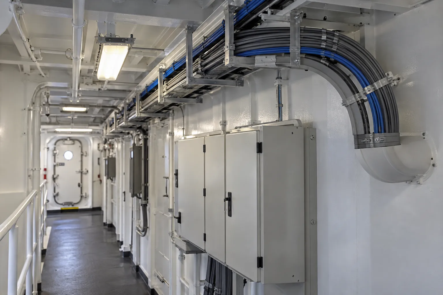
Vessel location, cable access, interfaces and attendance windows shape the agreed installation. The diagram illustrates system relationships, not a completed vessel project.
Plan copper data cabling aboard a commercial vessel. Explore the decisions that shape the installation, interfaces and handover.
Onboard copper cabling is shaped by compartment access, existing containment and the vessel’s material and installation requirements. Confirm the approved cable and termination specification with the responsible team rather than choosing solely from a category name. A Cat6 or Cat6A link still depends on suitable components, routing and workmanship. Identify which parts of the route can be accessed during attendance and who is responsible for any penetrations or reinstatement. Keep the communications scope distinct from work that requires separate approval or specialist attendance.
New cameras, access points and workstations may need local network connections in spaces served by different cabinets. Map both endpoints and the intended switch connection before pulling cable. Existing labels may no longer match the physical arrangement, so include identification work where records are uncertain. During repairs or additions, agree which services may be disconnected and how restoration will be witnessed. A useful handover relates each outlet or equipment connection to its panel and test record, with inaccessible or retained links clearly identified.
Confirm vessel-specific materials, routes and responsible interfaces.
Map equipment endpoints to the correct cabinet and patch field.
Record agreed copper-link checks and service restoration within the attendance window.
Use these checkpoints to discuss the scope. The final test method, responsibilities and acceptance evidence depend on the selected system and agreed work.
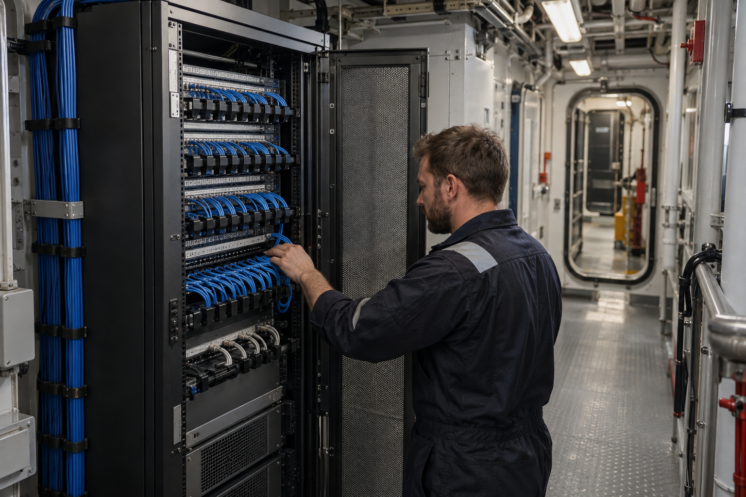
Maritime structured cabling starts with an endpoint schedule for the agreed vessel areas. Include office equipment, wireless access points, cameras and other supported devices. Establish the cabinet serving each location and whether existing routes can be used. The vessel team must confirm applicable material and installation requirements before selection. A convenient route on a general arrangement drawing may have access or segregation constraints that need to be resolved aboard.
Trace connections before adding cables to an occupied tray or communications cabinet. Agree how retained live cables will be identified and distinguished from new runs awaiting termination. Coordinate penetrations or reinstatement with the responsible vessel specialists. If an attendance window is short, define a stage that can be left clearly identified for the next visit. Incomplete links should not be confused with accepted connections, particularly when another team resumes the work.
Use identifiers that the crew and shore support can both interpret. The outlet record should lead to a cabinet termination and the agreed test result. Note route changes and inaccessible locations instead of repeating an outdated design. If a fleet uses a common specification, keep vessel names and local cabinet references explicit. Future additions can follow established records while accounting for the actual onboard layout and remaining capacity.
Explore installation requirements, interfaces and the information needed before work begins.
Ship network cabling can pass through machinery, technical and accommodation spaces before reaching a camera, workstation or access point. Review cable routes, access and any proposed penetrations with the vessel team; do not assume a commercial-building route or cable specification is suitable onboard.
Cat5e (Category 5e), Cat6 (Category 6) and Cat6A cabling choices are assessed against the application, existing infrastructure and vessel requirements. Patch panels, data outlets and network cabinets need clear identification across decks and areas. Coordinate local PoE device connections with the copper and fibre backbone infrastructure.
Before attendance, provide the vessel location, deck or area plans, existing cabinet details, fault symptoms and the permitted work window. Identify equipment replacement and connections that must remain available. Repairs during vessel attendance may include fault finding, retermination or replacement within the agreed scope.
Agree testing and documentation with the technical contact before work begins, including any required certification/testing records. Handover maps installed connections to decks, areas and cabinets and distinguishes completed work from follow-up items. Multi-vessel and international port requirements are assessed around access and the technical scope, without implying completed offshore projects.
Onboard data cabling supports the switches, wireless access points and equipment racks that distribute vessel connectivity. When a Starlink installation or IT upgrade is planned, identify the new terminal-to-network route and any additional copper or fibre connections before attendance.
Coordinate the cabling schedule with the active-network team so labels, patch-panel positions and testing records match the configuration handover. Physical cable installation and logical network segmentation have different roles; agreeing both makes the boundaries between CCTV, business IT and other supported systems clearer.
We review the proposed route with the vessel team, including access restrictions, existing containment and any work requiring coordination with other contractors. Vessel-specific material and route requirements form part of the specification.
Yes. Existing terminations, cabinet capacity and equipment connections are reviewed during scoping. We identify what can be retained and what needs changing.
Work can be scoped around specific faults or equipment locations. Testing helps determine whether a local repair, replacement run or wider upgrade is appropriate.
Commercial sites. International programmes. Onboard systems.
Installations across all of the US, Europe, the Caribbean, the UK and South Africa, with deployment support in Canada and Panama.
Regional resources · Fly teams · International project support
Explore regions & deployment hubs → DEPLOYMENT NETWORK / ILLUSTRATIVE CONNECTIONS