
Leak Detection Monitoring
Leak detection is often most useful when it connects a suitable physical sensor to a clear facilities response. A water-sensing cable, point sensor, compatible environmental device or supported visual application can help surface a possible leak for review. The aim is to tell the responsible team where a condition has been detected, what information is available and what action should follow.
Video unavailable. Follow the illustrated workflow below.
THE EVENT JOURNEY
Sensing cable → gateway → facilities alert
Water reaches the area
A leak enters a monitored technical-room location or reaches a sensing cable.
Identify the event
The sensor gateway, or supported visual analytics, associates a possible event with a known location.
Send local and remote alerts
An approved LAN/WAN path can deliver email, SMS, app or monitoring events. Remote and vessel sites may use mobile, Starlink or VSAT backhaul where deployed.
Investigate safely
Facilities or vessel teams verify the location, follow the response plan and record the outcome.
Illustrative sequence, not a detection-speed demonstration. Capabilities and notification channels depend on the selected equipment, platform and agreed response workflow.
Choose the sensing method for the location
A sensor can detect a condition at its installed position, while a camera can only show what is visible within its view. Water behind equipment, below a raised floor or inside an enclosure may be outside that view. Visual leak recognition is a platform-specific capability and should not be assumed available on every camera.
For many technical-room applications, a dedicated leak sensor or sensing cable is the more direct event source.
The scope should identify the likely source and route of a leak, the surfaces being monitored and the equipment that needs protection. A point sensor covers a different area from a routed sensing cable. The installed arrangement must remain accessible for inspection and compatible with the environmental conditions.
The design should also distinguish water detection from humidity, condensation, temperature and other environmental measurements.
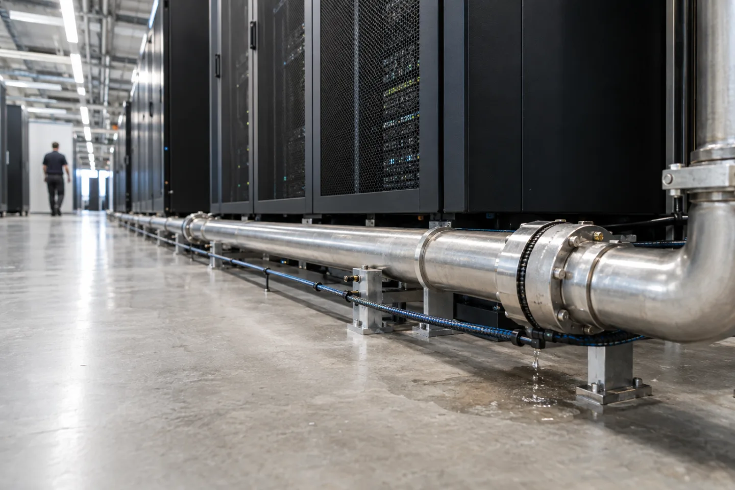
Make the location information actionable
A notification saying only that a leak has occurred somewhere on a site is difficult to use. Label the sensor zone, gateway and physical area so the receiving team can find the relevant location without guessing. In a larger facility, a site identifier, room name and equipment reference can be more useful than a technical device address.
Keep those labels aligned with the installation and handover records.
A nearby camera may support remote verification or help someone understand access conditions, but it does not automatically confirm the source or severity of the leak. Where a sensor gateway exposes several zones, the monitoring interface should preserve that distinction.
An event from a technical room, loading area or plant space should reach the people who are authorised and equipped to respond there.
Use cases across operational environments
Commercial facilities may monitor cooling equipment, service risers or vulnerable technical spaces. Warehouses may need awareness around plant areas, roof drainage-related locations or equipment rooms, depending on the actual risk assessment. Network and IT spaces can benefit from a defined environmental event route that reaches facilities as well as the IT team responsible for nearby equipment.
Industrial, remote and maritime installations require particular attention to environmental suitability, access and the existing monitoring arrangements. A general-purpose building sensor is not automatically suitable for every vessel or industrial compartment. Agree the installation conditions, responsible system owner and support boundary.
Where dedicated safety or process systems are required, an operational leak notification should not be represented as a replacement for those systems.
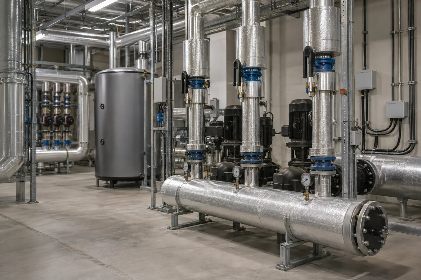
Connect the sensor to the response team
A supported sensor or gateway sends its event through the agreed wired or wireless network to a monitoring platform. The event can then produce an email, text/SMS notification, mobile app alert or control room entry where the relevant integrations are available.
Some installations may use a local audible indication or an alarm output, but the interface and purpose must be explicitly designed.
An automated shut-off or equipment isolation function is a separate control decision with potential consequences. It should never be implied by the presence of a leak alert alone. The normal operational workflow may be to acknowledge the event, verify the location, arrange attendance and follow an authorised isolation procedure if required.
Delivery, acknowledgement and escalation records help determine whether that process works during nights, weekends and staff changes.
Check the full installation rather than only the dashboard
Commissioning should verify each installed zone using an approved method for the selected sensor. Check the displayed location, message content, recipients and reset behaviour. Test what the platform reports when a sensor, gateway, power supply or network path becomes unavailable.
A failed monitoring connection should be visible as a fault, not mistaken for a dry environment.
After cleaning, maintenance or equipment movement, confirm that sensing cables and point sensors remain correctly positioned. Agree inspection responsibilities, battery replacement where relevant, retention of event records and access to the monitoring platform. IS Security can scope the sensor connections, gateways, network infrastructure and alert integration as a coordinated installation, with clear handover information for the facilities and technical teams who will use it.
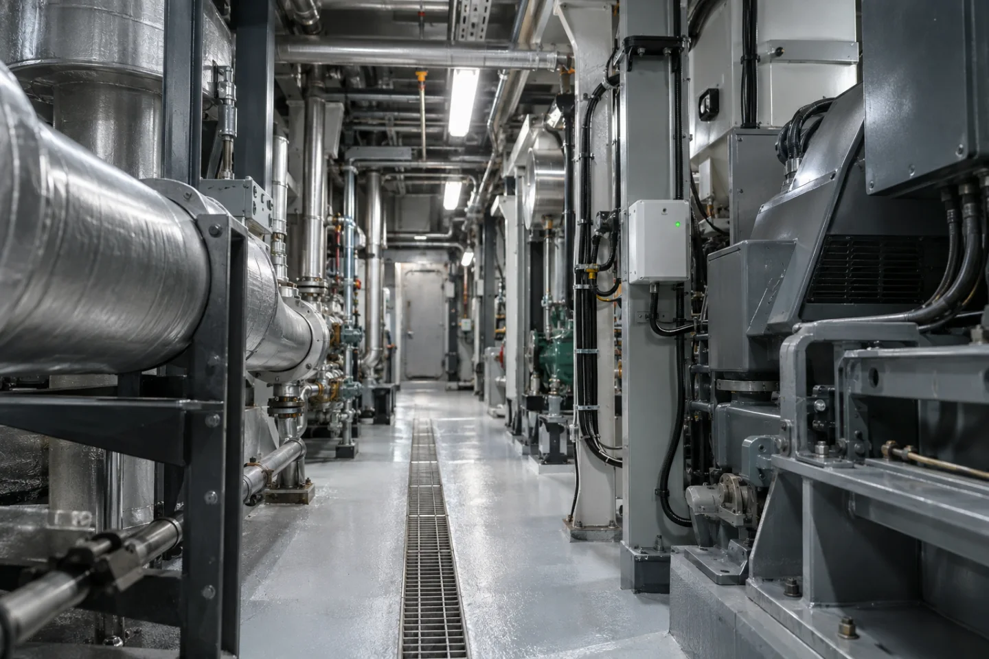
From a possible event to a useful response.
Sensing cable → gateway → facilities alert. Open each stage to explore its role. This is an illustrative workflow; it does not analyse live footage or send notifications.
01 / OBSERVELeak sensing cable / spot sensor
The monitored condition is: water reaches the monitored location. Select the device, field of view and installation position for this specific task. Record obstructions, lighting, power and maintenance requirements before relying on the event stream.
02 / INTERPRETSensor gateway + event interface
Apply location identity and sensor health. The selected platform must support the intended event and expose a usable interface. Test representative events and unwanted triggers; an analytics output is a candidate for review, not proof of what happened.
03 / CONNECTLAN → firewall → secure platform
Carry authorised event data through the local switch or sensor gateway and an approved network path. Size bandwidth for any accompanying clip. Protect accounts and interfaces, supervise connection loss and agree retry behaviour where the platform supports it.
04 / RESPONDFacilities / maintenance team
Deliver the location, event type and time to the agreed recipient. A person verifies the available context, follows the site response procedure and records the outcome. Delivery, acknowledgement and resolution are different states and should be reviewed separately.
Where supported by the selected camera, sensor, VMS or analytics platform. Safety-related analytics provide supplementary operational awareness and do not replace dedicated certified fire or life-safety systems where required. The final design must define the equipment, event interfaces and responsible response team.
Reach the people who can act.
Available outputs depend on the selected platform, licences and agreed integrations. Open a channel for practical delivery considerations.
Send event context and a secure review link to an authorised mailbox where supported. Agree recipients and inbox monitoring; acceptance by a mail server does not confirm that a person has read or acted on the message.
Text / SMS
Use a supported gateway or monitoring integration for concise location and priority messages. Confirm service availability, costs and delivery reporting. Sensitive footage should stay within the authorised platform rather than an unrestricted text message.
Mobile apps
A supported application can present event details and acknowledgement controls to authorised users. Test notification permissions, connectivity and out-of-hours coverage. A silenced or offline handset needs a planned alternative recipient or escalation route.
Alarm outputs
A compatible interface may trigger an approved operational sounder, relay or indicator. Define supervision, reset behaviour and responsibility. Do not connect analytics directly to hazardous equipment or alter certified safety functions without the appropriate engineered design.
Control room / monitoring platform
Route supported events into the operator workflow with a consistent site identifier and priority. Give reviewers enough context to distinguish an actionable event from an unwanted trigger, with access restricted to their responsibilities.
Escalation & event review
Define who receives an unacknowledged event, how long the initial team has to respond and how closure is recorded. Review failed deliveries, recurring unwanted alerts and staffing gaps alongside the detection rules.
Plan the complete monitoring chain.
Start with the event, the operating environment and the person responsible for responding. Share existing equipment details, site plans and integration requirements with the technical team.